BALSA WOOD BRIDGE
Engineering for a specific material
INTRODUCTION
This website will cover the design, construction, and testing of a model bridge made out of balsa wood and glue. This bridge also includes a lifting mechanism, which does not need to be made out of balsa wood, and can use a motor, pulleys, or any other mechanism to lift the bridge. In order for the bridge to be a success, it needed to meet certain criteria. The bridge needed to span a length of at least 400mm, so that it could reach steel abutments on either side of the span. Aside from this, the bridge needed to remain under 85 grams in weight, exceeding the lifting mechanism. These two criteria would be the first focus when designing the bridge, as they will determine the fitment of the bridge in the apparatus. Aside from this, the bridge must be designed to fit a 38mm wide road deck, to support a simulated scale vehicle that is 30mm by 25mm in size.
The most pressing criteria pertains to how much weight the bridge will need to be able to support. Loaded at the center of the bridge, a 20kg weight will be hung from the bottom deck, to test if the bridge fails, as well as how much the bridge will deflect. The bridge must not deflect more than 25mm. The bridge also must be capable of lifting 140mm above its original resting plane, to allow passage underneath. This lifting process must complete a full cycle (lifting up, holding for 10 seconds, then dropping back down) within a 60 second period. These criteria for functionality will be regularly tested, to ensure the success of the bridge.
Bridge Design
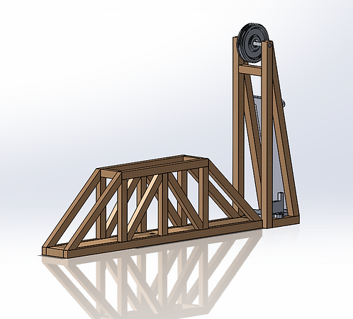
Image 1

Image 2
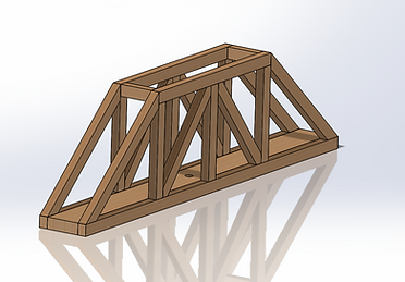
Image 3
Spring Quarter Presentation Video
Video 1
Fall Quarter Presentation Video
Video 2
Link To Proposal
Results
Articulation Cycle
Time Raw Data
Force vs time
Raw Data
Deflection vs Time
Raw Data
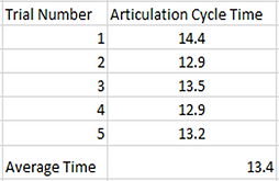
Table 1
The image above shows the tabulated results for the articulation cycle time test, while the graph of the results can be seen in the top graph in the lower middle column (figure 5). These show the time that each cycle took when testing, as well as the raw data from which the average cycle time of 13.4 seconds was calculated.


Table 2
Table 3
Pictured above is the simplified raw data for the load test, which shows the load on the bridge’s center in kilonewtons
Table 3 shows the data collected as the load was slowly applied on the Instron machine, tracking the deflection in mm.
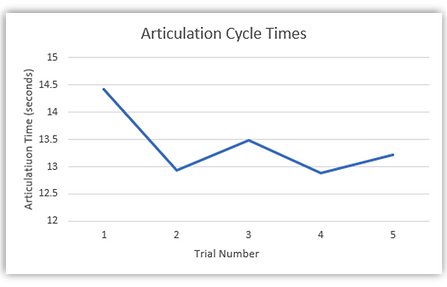
Figure 1
The above graph shows the trends regarding the results of the articulation cycle time test. This test was done to find the average time it took for the bridge to complete a “full” articulation cycle (raising completely then holding for 10 seconds, then lowering back down). The average cycle time was calculated to be 13.4 seconds.

Figure 2
This graph shows the results of the force loading test, which was carried out in order to determine whether or not the bridge met the requirement of being able to support a 20kg load, or 190 Newtons. The results of this test showed that the bridge met the 190 Newton requirement. The fluctuation seen is the reflection of the bridge “setting” into the apparatus. No breaks were found post-loading, supporting the theory that the bridge was adjusting into the apparatus.
Figure 3
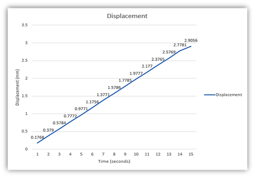
The graph above shows the physical behavior of the bridge as the load increased. The graph shows the deflection from the original plane in millimeters. The resulted maximum deflection when experiencing 190 Newtons was 2.9mm. This test was efficient in showing the rigidity and strength of the bridge, as well as how consistent the deflection moves. Seen above, the linear shape of the graph demonstrates no inconsistencies.
Results Summary
The results of the tests carried out on the bridge showed how the bridge efficiently met all the requirements listed in the analysis section. The tests were done with minimal margin for error, due to simplistic nature of many of the tests (such as measurement and dimension testing). The Instron machine provided ample data regarding deflection and load, demonstrating the bridge withstood 19kg with only 3 mm deflection.