Analysis
Balsa Wood Bridge Requirements
1. The bridge’s structure must be constructed using only balsa wood and glue. Other non-structural components such as gears, pulleys, and shafts do not need to be made of balsa wood.
2. The bridge’s weight must not exceed 85 grams, or 0.187 pounds, when the articulation components are removed (balsa wood only).
3. The bridge must span longer than 400 millimeters or 15.75 inches, to reach the abutments.
4. Must fit a 38-millimeter-wide road deck along the bridge.
5. Road deck must be within 12 millimeters from the steel abutments
6. Midpoint of bridge must be able to split, and then raise 140 millimeters above its initial resting position.
7. Bridge must hold the 140 millimeters ascended position for a minimum of 10 seconds.
8. The lifting and dropping mechanism of the bridge must complete its cycle within 60 seconds.
9. The bridge must be able to support at least 18.9-20 kilograms, with a maximum vertical deflection of 25mm.
10. Must allow a 30mm by 25mm object to traverse across the whole bridge
Most Important Analyses for Bridge Success
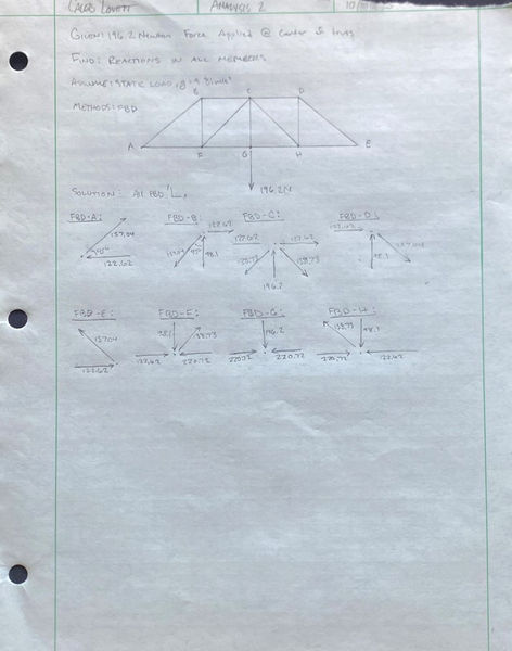
Reactions in Beams
Using the method of joints, the internal reactions for each of the members of the truss were able to be found. The image to the left shows each force in each member, and whether they are under tension or compression. This analysis was done early on to ensure that the design would be able to evenly distribute the force across the design.
Image 1

Stress In Beams
This analysis covered the stress in each of the members of the truss. The first analysis for the reactions in the beams along with the cross sectional area of the beams was used to determine the stress that each member would be experiencing. The results were all under the maximum stress that balsa wood could handle, meaning the design was able to withstand the 20kg load.
Image 2
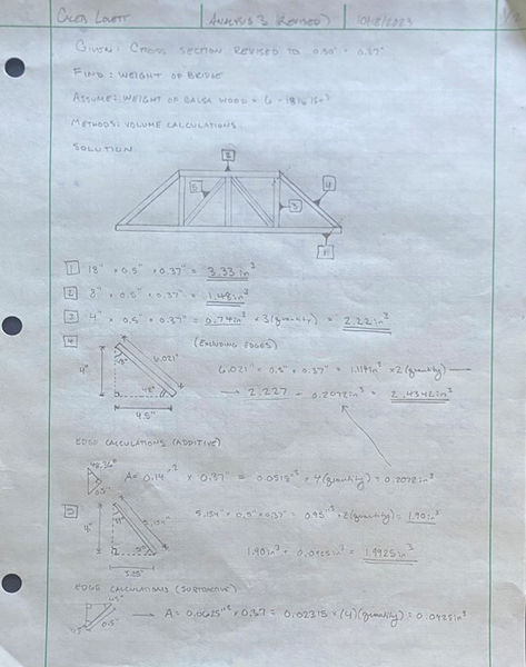
Bridge Weight
This analysis covered the weight of the bridge as a whole, based off of methods of geometry and volume calculations. First, the geometry of the design was analyzed, to find the angles of the end beams, which would be needed to find the volume of the truss. The dimensions of the angled beams were found using Pythagorean's theorem.
Image 3
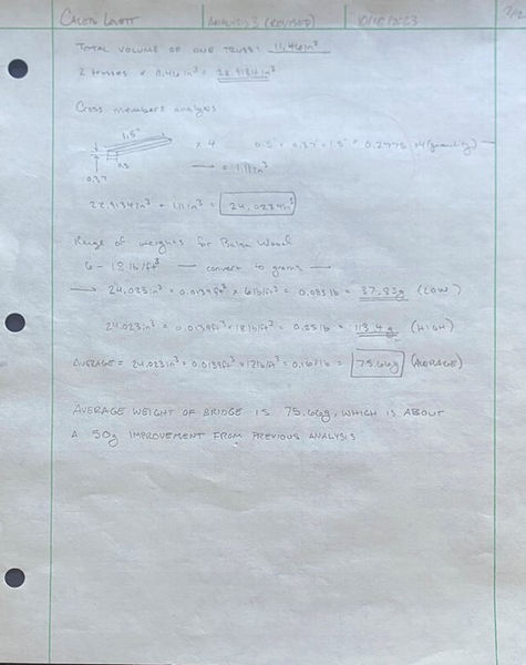
Bridge Weight Cont.
The image to the left shows the continuation of the previous analysis. This page covers the calculations for the weight of the bridge. The total volume of the bridge was found to be 24.023 cubic inches, which was then multiplied by two constants. These values were the high and low end density of balsa wood. This resulted in two results and an average. The lowest weight was found to be 37.83 grams, while the highest was 113.4 grams. The average weight of the bridge was found to be 75.66 grams.
Image 4
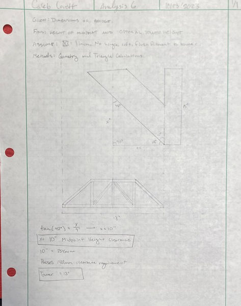
Bridge Angle and Height
This analysis tackled a more simple yet important issue. The bridge angle at the ends needed to be able to allow the bridge to lift 140mm at the center of the bridge. To analyze this, the angle of the current bridge design ends was placed in the upright position, and the height was measured. Due to the 42 degree end angle, the bridge was actually able to raise a total of 254mm upward.
Image 5
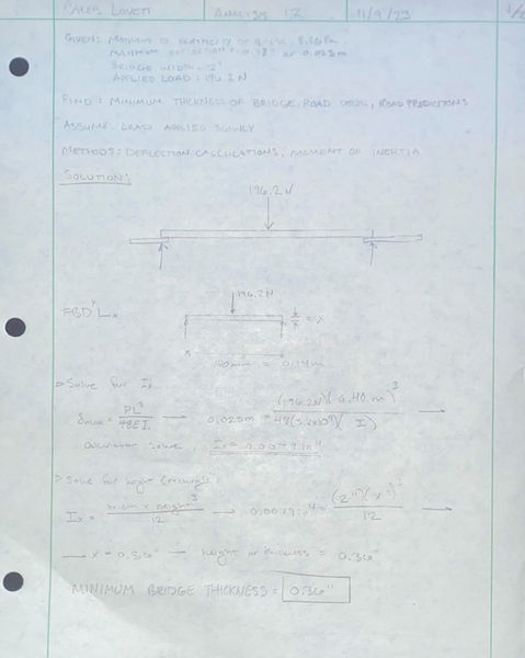
Road Deck Thickness
This analysis used deflection equations to find the minimum road deck thickness required to ensure that the 25mm deflection requirement was met. Starting with a maximum deflection of 25mm, the unknown I was solved, given that the road deck was 2 inches wide. From isolating I and solving for the missing dimension, the minimum road deck thickness required was found to be 0.36".
Image 6