Bridge Construction

Drawing Tree
Figure 1
Total Manufactured Parts

Figure 2
Pictured above is a photo of the truss members of the bridge prior to gluing. These are laid out in the general truss design of the bridge, along with the cross members on the corners to show where the bridge would be supported.

Figure 3
Pictured above is a photo of bridge partially assembled and glued. The bridge is not fully assembled due to the electronics and hinge not yet being installed. However, this shows the location of the glued joints along with how the tower assembly will generally look. A 3d modeled motor mounting bracket will be printed later on to improve speed and ease of removing the articulation components.

Figure 4
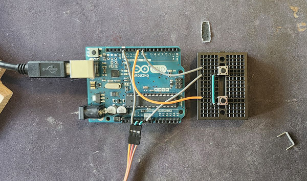
This picture shows the Arduino Uno circuit that was used for the articulation sequence. Seen on the left is the usb-b plug used to supply power to the system, which currently plugs into a computer or wall outlet (with wall brick adapter). The two buttons on the bread board to the right have to different purposes, with the top button being used for lowering the bridge, and the lower button being used for raising the bridge. These controls were on a timer thanks to the Arduino code, and allow precise lifting of the bridge.

Figure 5
This view of the bridge shows how it stands after the hinge was installed. This allowed the bridge to stand on its own, and upon assembling, the weight difference between the bridge and the tower was very noticeable. The tower weighed significantly less, meaning that there would need to be the use of some weights to counteract the weight of the bridge as it moved. Until the exact size and quantity of weights is determined, it will simply be held down by hand for demonstration purposes. The bracket that holds the articulation pieces will also have a spot for weights to attach to, in order to make the ease of use higher.

Figure 6
With the electronics now attached to both the bridge motor, my personal computer, and fresh code uploaded to the Arduiuno board, the bridge at this point was completely ready for testing its functionality. The final test can be seen in the construction video below.
Figure 7
This video highlights some of the process used to create the balsa wood bridge. The beginning of the video shows the gluing and clamping process, and eventually the working bridge is demonstrated at the end of the video.
Construction Methods
To construct the bridge in a way that holds true to the original design, a meticulous construction plan was needed. During the manufacturing process, there were steps taken to guarantee accuracy and reduce waste. The first step in the process was marking the dimensions on the wood sticks, using printed off documentation as reference. After the dimensions were marked, the sticks were cut with a table saw, to create a cross section of 0.5" by 0.37". After the cross section was measured and passed the quality check, the pieces were cut to the proper length, per documentation. Due to the inability to make a straight cut with the table saw while holding the stick sideways, the bandsaw was used. This allowed slow, precise cuts that were extremely accurate. For some of the parts, this is where their manufacturing process ended. However, some more complex parts required more attention after this point.
Some of the parts required cuts at the ends that were not perpendicular to the length of the stick. To create accurate and straight angles that adhered to the documentation, an angle measuring tool specific for wood working was used. This ensured that the angles of the parts would fit snug to the other parts, and minimal adjustments would need to be made down the line.
All of the pictured parts were created with a maximum tolerance of 0.1" in mind, which was not exceeded in the manufacturing process.
Once the bridge members were created, the gluing process could begin. The bridge members were glued and clamped together according to the assembly documentation created. This process was simple, but took several days to complete, do to the long bonding times of the wood glue purchased. Once the bridge was glued and bonded together, the bridge was then assembled using the remaining components; the hinge, baseplate, fishing line, and electronics. This portion of the construction process took quite some time as well, learning to program and install the Arduino board correctly and efficiently. As a result of rigorous experimentation, the bridge can now articulate within the requirements of the bridge performance.